The traditional product design cannot fundamentally solve and generally grasp the issues of product design time, quality, and cost, and thus cannot meet the ever-changing and continuously-developing market demands. To make agile responses to rapidly changing market demands, we must seek advanced design methods and methods. The virtual prototype technology is based on computer-supported simulation technology. In the product design stage, the entire process of product design can be simulated in real time. The virtual prototype of the computer simulation predicts the product structure, product performance, product manufacturability and The product manufacturing cost reduces the trial production links in product development, so as to achieve the shortest product development cycle, the lowest cost, and the best product design quality. Therefore, we applied the virtual manufacturing technology to the design and development of the folding machine tool. In the conceptual design stage, the system simulation software was used to simulate the movement of the system. The entire system was analyzed, and the deficiencies and defects in the design were found and modified in a timely manner. Until you get the optimal design plan, make a physical prototype. This greatly accelerates product development progress, reduces product development costs and costs, and obtains optimized design products.
1 Structure design of a folding machine
The drive system of the folding and shearing machine is currently widely used as a hydraulic drive driven by a double cylinder, which has a high cost and a poor synchronism of the slider. This machine adopts the hydraulic medium-moving single-cylinder drive, the symmetry linkage force-increasing mechanism and the gear synchronous mechanism transmission, which not only solves the synchronization problem, but also realizes the increase of force, and has the advantages of simple structure, compactness, and easy maintenance.
2 Folding and shearing machine virtual prototype model simulation software platform
ADAMS (Automatic Dynamic Analysis of Mechanical Systems) is a virtual prototype analysis software developed by the United States MDI. The software uses an interactive graphical environment and parts library, constraint library, and force library to create a fully parametric mechanical system geometry model. The solver uses the Langrage equation method of multi-rigid system dynamics theory to establish the system dynamic equations, The mechanical system performs statics, kinematics, and dynamics analysis, and outputs displacement, velocity, acceleration, and reaction force curves. The simulation can be used to predict the performance of a mechanical system, the range of motion, collision detection, peak load, and input loads for finite element calculations.
However, because the focus of this software is on the mechanical analysis, there are still many deficiencies in modeling, especially the three-dimensional modeling of some complex parts is difficult to achieve. Therefore, SolidWorks software is used here to perform solid modeling of part and assembly of folding machine tool, and then the assembly file is Paras01 supported by both ADAMS and Solidworks. The id format is entered into ADAMS. Static, dynamic, and kinematic simulations can be performed by adding initial conditions such as mass, force, constraints, and motion to each part in ADAMS. Based on the combination of the two softwares, a simulation study of a folding machine tool is realized.
3 Creation of a Virtual Prototype Geometric Model for a Folding Machine
SolidWorks is an excellent 3D modeling software based on Window/NT/2000/XP. It can be used for 3D part design and 3D virtual assembly. It can also dynamically simulate the transmission relationship between components through three-dimensional assembly drawings. Therefore, it has been widely used in product development and has become the mainstream design tool for three-dimensional modeling of mechanical products.
In SolidWorks, the three-dimensional model of each component is first established according to the actual size, and then the bottom-up assembly technology provided by SolidWorks is used to create a virtual assembly model according to the actual assembly position relationship of each component, as shown in FIGS. 1 and 2 . And use SolidWorks to provide "interference inspection" and "physical simulation" tool static interference inspection and dynamic collision inspection of the assembly, in order to identify problems and timely modification. Finally, save the machine tool assembly file as a Parasolid format graphic file to reduce the data loss when the assembly model is imported into the ADAMS environment.

After the above work is completed, the bending machine tool assembly model created in SolidWorks can be imported into ADAMS for simulation analysis, which provides a theoretical basis for the optimization of work parameters and structural design parameters of the folding and shearing machine tool.
4 Virtual Prototyping Analysis
4.1 Importing an Assembly Model into ADAMS
First set the same units as Solidworks in the "Units Setting" dialog in ADAMS. Then open the Parasohd-format folding machine assembly file and import it into the ADAMS/View environment.
4.2 Constructing a Virtual Prototyping Simulation Model in ADAMS
First, add the marker points to the imported geometry model, and calculate the coordinates of each point according to the geometric relations. If the material properties of the part in the model do not match the actual ones, you can redefine it in the property modification dialog to make it meet the requirements. Use the combined shape commands in the geometry modeling tools provided by ADAMS to combine related parts into one component. Such as the left and right wallboard, upper fixed board, table, etc. combined into a rack. Use the constraint library in ADAMS/View to add constraint pairs between links to define the motion relationships between the various components. If a fixed pair is added between the frame and the ground, a slider along the y axis is added between the slider and the frame, the slider and the upper link, the upper link and the cylinder, the upper link and the lower link, and the lower Each connecting rod and synchronous link, the lower link and the frame, the synchronous gear and the frame, the synchronous link and the synchronous gear are each added with an x-axis rotation pair, and a gear pair is added between the two synchronous gears and the cylinder is A pair of movement along the z-axis is added between the pistons. This completes the establishment of a virtual prototyping model for a machine tool. As shown in Figure 3.

4.3 Simulation
The movement accuracy of the slider directly affects the work performance of the folding machine tool. In the virtual prototype model, the movement of the slider relative to the rack along the Y-axis direction is the main movement of the bending and shearing machine tool. Its kinematic performance reflects the bending and shearing machine tool and power. Simulation, to obtain the dynamic changes of the displacement, speed and acceleration of the slider and the output force of the slider to achieve the optimal design of the product. Use the function F(time,...)=SIGN(98000,-VX(zjje.huosai.MARKER_147) provided by ADAMS/View to define the thrust applied to the piston rod. Given a total simulation time of 2 s, the simulation step size is 200, Simulate, and then use the post-processing display to get the displacement, velocity and acceleration curves of the main components such as the slider, as shown in Figure 4 to Figure 9.

4.4 Analysis of Simulation Results
Fig. 4 is the displacement curve of the slider. The moving distance of the slider in the 2.5 s is about 50 nun, and the displacement curve is basically a straight line, which shows that the movement is stable, there is no vibration phenomenon, and it meets the performance requirements of the machine tool. Fig. 5 and Fig. 6 show the slider speed and acceleration curves, respectively. They have sharp changes at 1.75 s and all begin to increase sharply. This is consistent with the angular velocity and angular acceleration curves of the linkage force increasing mechanism in Figs. 7 and 8. , Fully in line with the rapid return characteristics of the planar linkage. This feature also meets the process requirements for cutting and bending. Figure 9 shows the force output by the slider in the y-axis direction, ie the bending force. It can be seen from the figure that the bending force gradually increases, and the force increases to a maximum of 650 kN at about 2.5 s (the position at which the bending begins), which is in full compliance with the force-increasing characteristics of the planar linkage mechanism.
According to the simulation results, the design of the folding machine tool is optimized and a physical prototype is produced. Through testing, it can be seen that the assembly system performance, movement performance and output force of the mechanical system of the folding and shearing machine fully meet the performance requirements of the folding and shearing machine tool.
5 Conclusion
The SolidWorks software was used to complete the three-dimensional model of the mechanical and mechanical components of the dual-use machine tool and the interference and collision check. The assembly model was imported into ADAMS through parasolid format. A virtual prototype simulation model of the bending and shearing machine tool was established. The initial and boundary conditions were set. The simulation results of the slider's mechanical and kinematic characteristics were used to obtain the most accurate results, and the physical objects were manufactured. Prototype, through the prototype test, all performance indicators meet the design requirements, stable and reliable performance.
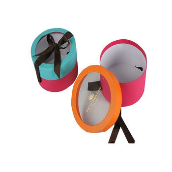
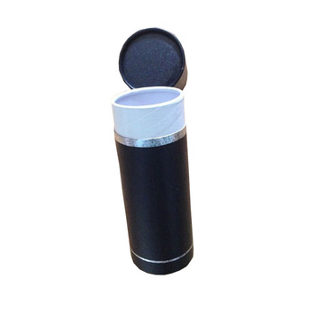
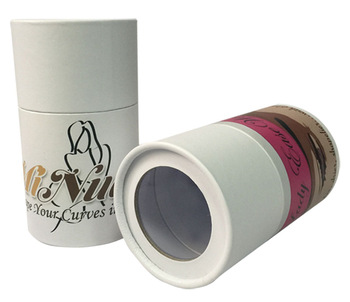
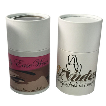
Paper tube round box is one of our unique shape of the boxes. In general, it is used to the candy packing, candle packing, cosmetic packing, and underwear packing. The paper tube round box as the candy box, there are display window and decoration ribbons. When it used to the candle, maybe just do the base without lid. If as the cosmetic box, paper tube round box will be luxury and exquisite appearance. The white paper tube round box especially suitable for close-fitting clothes, give a person the feeling of clean.
The candy and candle packing are usually made of coated paper, white cardboard. The size is smaller. Looks like very itsy-bitsy. Make the person can't help to have the urge to buy candy. Would you be want to experience the charm of it?
The material of cosmetic box and underwear box is high-quality grey cardboard and art paper. It make the paper tube round box into the luxury gift box.
Please refers pictures of paper tube round box:
1. Candy box
2. Cosmetic box
3. Underwear box
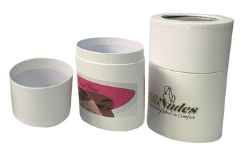
Round Tube Paper Gift Box,Kraft Paper Round Tea Box,Round Tube Macarons Box,Round Cardboard Box
Guangzhou Mingyin Packaging Trading Co.,Ltd. , https://www.mypaperpackages.com