Abstract: The characteristic length of micro-combustion system is very small. Its flow, heat transfer, and combustion characteristics are different from those of large-scale combustion systems. In the experimental study of micro-combustion, accurate measurement of micro-fuel flow is a key part of the experiment. The article introduced several domestic methods for the measurement of liquid and gas micro-flows, and reviewed the measurement principles and performance of the measuring devices. For workers in the field of micro-electromechanical and metrology inspection.
Keywords: micro flow, micro-combustion, liquid flow meters, gas flow meters, micro-electromechanical At present, MEMS devices are attracting more and more attention of scholars. At the 1989 meeting in Salt Lake City, USA, the MEMS concept was first proposed: Micro -Electro-MechanicalSystems, that is, microelectromechanical systems, which refers to devices that feature electronic devices and mechanical devices with feature sizes ranging from 1 μm to 1 mm. The study of micro-combustion is the basis for the manufacture of micro-electromechanical devices, and the precise measurement of micro-fuels is a prerequisite for the experimental study of micro-combustion. Micro-flow measurement and control system is an important direction of micro-mechanical research, and it is also a major technical measure of micro-fluidic precision measurement and control. The technical background of the microfluidic system research is the maturity of micromachining technology, and the application background is the special occasion that the flow and viscosity requirements of some conventional fluid systems cannot meet. After the micro-flow system has matured, it can even replace some of the current products. The flow rate of the microfluidic system is in the order of nL/min~L/min. Due to the small size, the system can reduce the ineffective volume, reduce energy consumption, and increase the response speed.
In the preliminary micro-scale diffusion combustion experiments, we have a preliminary understanding of all aspects of the micro-flame characteristics. As experiments are carried out in more detail, accurate measurement of micro-flows will be a critical link. Because the error between the actual supply value and the measurement value of the micro flow will directly affect the accuracy of the experimental results. Although researches on micro-flow measurement at home and abroad started relatively late, with the deepening of theoretical research and the accumulation of practical experience, there is a more concrete and profound understanding of the difficulty and existing problems of micro-flow measurement, through continuous improvement. With perfection, micro-flow measurement technology has been continuously developed.
1 The measurement of liquid micro-fuels The flow rate of domestic liquid flowmeters on the market can only reach a few hundred milliliters per minute. Imported flowmeters generally have a minimum flow rate of tens of milliliters per minute, but they are expensive; however, standard differential pressure flowmeters are generally used. Plate hole type, nozzle type, Venturi tube type, etc., its rated flow is larger, measurement accuracy is lower, usually the error is more than 5%. Can not meet the requirements of liquid micro flow metering.
1.1 Thermal Liquid Mass Flow Meter The experts of the Flow Meter Association of China Instrument Industry Association have provided an overview of the measurement principle, performance and application of thermal flow meters.
Thermal flow meter from the measurement principle, can be divided into two categories: 1) the use of flowing fluid to transfer heat to change the wall temperature distribution of the measurement of the heat transfer distribution effect of the heat distribution flowmeter, formerly known as calorimetric flowmeter; 2 ) The thermal Mass Flowmeter, which uses the heat dissipation (cooling) effect of the Kim's Law, is characterized by the insertion of a temperature measuring element into a measuring tube or pipe of a flow sensor, called an insert type thermal flow meter. However, the existing liquid micro flow thermal flowmeters are thermal distribution flowmeters.
Fig. 1 is a schematic diagram of the heating type thermal flowmeter, and Fig. 2 is a refrigerating type schematic diagram using the Peltier effect. The types of heated thermal liquid mass flow meters on the market include Liqu-iFlow and L-Flow models from Bronkhorst H-iTech in the Netherlands, and Flomega models from Brooks in the United States; and refrigerated thermal liquid mass flow meters on the market. The LF series of the American Estech company is seen. There are 9 full-scale specifications in the range of 0.01g/min~100g/min, and the response time is about 2s. Thermal liquid mass micro flowmeter is suitable for measuring liquid gas, mixing ratio of liquid medicine, raw material gasification supply system. Volume flow rate is as small as 10-6L/min~10-3L/min, or mass flow rate is 10-6kg/min~10-3kg/min.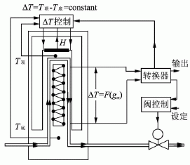
FIG. 3 shows a structural block diagram of a tubular differential pressure flowmeter detecting the water leakage of the thermostat. The flowmeter consists of a long throttle tube and a differential pressure sensor. In Fig. 3, the device under test is a thermostat for automobiles. It is necessary to detect the relationship between the water pressure applied to the thermostat and the magnitude of the leakage when the valve of the thermostat is closed. In order to make the pressure difference on the flow meter not affect the detection, the input pressure detection sensor of the device under test is placed at the inlet of the pressure liquid of the tested part. The input pressure of the tested part is provided by the pressure liquid and the pressure regulating valve; adjusting the pressure regulating valve can apply a series of different pressure values ​​to the tested part. The pressure value of the device added to the device under test is pj, the outlet pressure of the pressure regulator valve is pt, and the indicated value of the flowmeter differential pressure sensor is Δp. If line pressure loss is not taken into account, pt=Δp+pj. Since there is a certain relationship between the differential pressure value Δp and the flow rate at both ends of the flowmeter, the relationship between Δp and pj actually reflects the relationship between the leakage amount and the pressure of the device under test.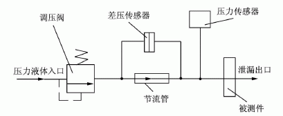
The specific application method is shown in Figure 4. The capillary tube with known internal diameter and length parameters is cascaded into the flow, differential pressure sensor is used to measure the pressure difference at both ends of the capillary, and then the capillary flow equation can be used to calculate the exact flow of liquid in the flow.
2 The measurement gas flow rate of gas micro-fuel is the amount of gas that passes through a certain section in a unit time. The state of the metered gas flow is described by three parameters: pressure, volume, and time. There are three methods for measuring the gas flow rate: if the gas pressure remains the same, by changing the gas volume measurement method, it is a constant pressure method; if the volume remains unchanged, by changing the pressure measurement method, it is a constant volume method; if Pressure and volume are changing, it is pressure change varactor method. It can be seen that according to the method of flow measurement, it can be divided into constant pressure flowmeter, constant volume flowmeter and variable pressure variable flowmeter. The variable-capacity variable-capacity flowmeter has a complex structure, is difficult to control, and has few practical applications. Generally, a constant pressure type flowmeter and a constant volume type flowmeter are used.
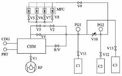
2.1 Constant Pressure Flowmeter Figure 6 shows the schematic of the constant pressure gas micro flowmeter. The constant pressure gas micro flowmeter can provide micro gas flow in the range of 3.96×10⁻⁴Pa•m3/s~3.64×10-8Pa•m3/s. The relative standard uncertainty in the range of 10-8 Pa•m3/s is 1%, and the relative standard uncertainty in the range of 1×10⁻⁷Pa•m3/s~1×10-4Pa•m3/s It is 0.7%. The principle of flow measurement is that when the gas flows into or out of the chamber, the capacity of the chamber is changed so that the gas pressure in the chamber is kept constant, then the flow of gas at Tr temperature (Tr is generally 23°C) can be passed. The pressure P, temperature T, and volume change rate dV/dt of the gas in the chamber were measured and calculated.
Q=-[d(P•V)/dt]•(Tr/T)=-P•(dV/dt)•(Tr/T)(dP/dt=0),(1)
Where: Q is the gas flow rate, unit: Pa•m3/s; P is the chamber pressure, unit: Pa; dV/dt is the volume change rate of the chamber, unit: m3/s; Tr/T is variable Room temperature change rate, dimensionless.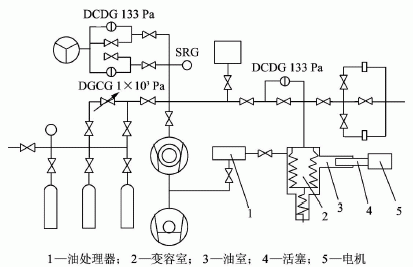
Keywords: micro flow, micro-combustion, liquid flow meters, gas flow meters, micro-electromechanical At present, MEMS devices are attracting more and more attention of scholars. At the 1989 meeting in Salt Lake City, USA, the MEMS concept was first proposed: Micro -Electro-MechanicalSystems, that is, microelectromechanical systems, which refers to devices that feature electronic devices and mechanical devices with feature sizes ranging from 1 μm to 1 mm. The study of micro-combustion is the basis for the manufacture of micro-electromechanical devices, and the precise measurement of micro-fuels is a prerequisite for the experimental study of micro-combustion. Micro-flow measurement and control system is an important direction of micro-mechanical research, and it is also a major technical measure of micro-fluidic precision measurement and control. The technical background of the microfluidic system research is the maturity of micromachining technology, and the application background is the special occasion that the flow and viscosity requirements of some conventional fluid systems cannot meet. After the micro-flow system has matured, it can even replace some of the current products. The flow rate of the microfluidic system is in the order of nL/min~L/min. Due to the small size, the system can reduce the ineffective volume, reduce energy consumption, and increase the response speed.
In the preliminary micro-scale diffusion combustion experiments, we have a preliminary understanding of all aspects of the micro-flame characteristics. As experiments are carried out in more detail, accurate measurement of micro-flows will be a critical link. Because the error between the actual supply value and the measurement value of the micro flow will directly affect the accuracy of the experimental results. Although researches on micro-flow measurement at home and abroad started relatively late, with the deepening of theoretical research and the accumulation of practical experience, there is a more concrete and profound understanding of the difficulty and existing problems of micro-flow measurement, through continuous improvement. With perfection, micro-flow measurement technology has been continuously developed.
1 The measurement of liquid micro-fuels The flow rate of domestic liquid flowmeters on the market can only reach a few hundred milliliters per minute. Imported flowmeters generally have a minimum flow rate of tens of milliliters per minute, but they are expensive; however, standard differential pressure flowmeters are generally used. Plate hole type, nozzle type, Venturi tube type, etc., its rated flow is larger, measurement accuracy is lower, usually the error is more than 5%. Can not meet the requirements of liquid micro flow metering.
1.1 Thermal Liquid Mass Flow Meter The experts of the Flow Meter Association of China Instrument Industry Association have provided an overview of the measurement principle, performance and application of thermal flow meters.
Thermal flow meter from the measurement principle, can be divided into two categories: 1) the use of flowing fluid to transfer heat to change the wall temperature distribution of the measurement of the heat transfer distribution effect of the heat distribution flowmeter, formerly known as calorimetric flowmeter; 2 ) The thermal Mass Flowmeter, which uses the heat dissipation (cooling) effect of the Kim's Law, is characterized by the insertion of a temperature measuring element into a measuring tube or pipe of a flow sensor, called an insert type thermal flow meter. However, the existing liquid micro flow thermal flowmeters are thermal distribution flowmeters.
Fig. 1 is a schematic diagram of the heating type thermal flowmeter, and Fig. 2 is a refrigerating type schematic diagram using the Peltier effect. The types of heated thermal liquid mass flow meters on the market include Liqu-iFlow and L-Flow models from Bronkhorst H-iTech in the Netherlands, and Flomega models from Brooks in the United States; and refrigerated thermal liquid mass flow meters on the market. The LF series of the American Estech company is seen. There are 9 full-scale specifications in the range of 0.01g/min~100g/min, and the response time is about 2s. Thermal liquid mass micro flowmeter is suitable for measuring liquid gas, mixing ratio of liquid medicine, raw material gasification supply system. Volume flow rate is as small as 10-6L/min~10-3L/min, or mass flow rate is 10-6kg/min~10-3kg/min.

Figure 1 warming principle diagram
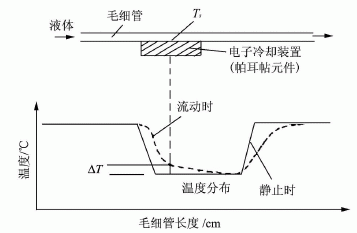

Figure 2 cooling principle diagram
1.2 Standard differential pressure flowmeter The tubular differential pressure flowmeter is an instrument for the detection of liquid micro leaks. Hubei Institute of Automotive Technology has designed a pipe differential pressure flowmeter to solve the measurement problem of large-scale micro-flow in thermocouple water leakage detection. FIG. 3 shows a structural block diagram of a tubular differential pressure flowmeter detecting the water leakage of the thermostat. The flowmeter consists of a long throttle tube and a differential pressure sensor. In Fig. 3, the device under test is a thermostat for automobiles. It is necessary to detect the relationship between the water pressure applied to the thermostat and the magnitude of the leakage when the valve of the thermostat is closed. In order to make the pressure difference on the flow meter not affect the detection, the input pressure detection sensor of the device under test is placed at the inlet of the pressure liquid of the tested part. The input pressure of the tested part is provided by the pressure liquid and the pressure regulating valve; adjusting the pressure regulating valve can apply a series of different pressure values ​​to the tested part. The pressure value of the device added to the device under test is pj, the outlet pressure of the pressure regulator valve is pt, and the indicated value of the flowmeter differential pressure sensor is Δp. If line pressure loss is not taken into account, pt=Δp+pj. Since there is a certain relationship between the differential pressure value Δp and the flow rate at both ends of the flowmeter, the relationship between Δp and pj actually reflects the relationship between the leakage amount and the pressure of the device under test.

Fig. 3 Block diagram of differential pressure flowmeter for detecting leakage
1.3 Capillary liquid micro flowmeter uses stainless steel capillary tube has a very stable seepage flow performance, and the liquid flow rate of the capillary tube is proportional to the pressure difference between the two ends of the capillary tube, and inversely proportional to the viscosity of the liquid. Accurately measure the pressure difference between the two ends of the capillary accurately. Liquid flow. Differential pressure measurement is a very mature technology. Using this characteristic of the capillary for liquid micro-flow measurement will give accurate measurement results. The advantages of this method are: 1 easy to use, in theory, can be placed anywhere in the process; 2 can be high temperature and high pressure; 3 data stability and high accuracy; 4 can achieve continuous measurement, output real-time traffic. The specific application method is shown in Figure 4. The capillary tube with known internal diameter and length parameters is cascaded into the flow, differential pressure sensor is used to measure the pressure difference at both ends of the capillary, and then the capillary flow equation can be used to calculate the exact flow of liquid in the flow.

Figure 4 Capillary metering principle
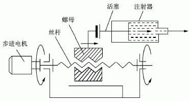
1.4 Medical microinjection pump The medical microinjection pump is composed of a stepper motor and its driver, a screw rod and a bracket, and has a reciprocating screw rod and a nut. Therefore, it is also called a screw pump. The nut is connected to the syringe's piston, which holds the liquid fuel. While working, the single-chip computer system sends out the control pulse to make the stepping motor rotate, and the stepping motor drives the screw rod to change the rotational motion into linear motion, pushes the piston of the syringe to inject the liquid, and outputs the liquid fuel in the syringe. By setting the rotational speed of the screw, the advancing speed of the syringe plunger can be adjusted to adjust the given liquid fuel. The structure is shown in Figure 5. 
Fig. 5 Structure of the microinjection pump
The range of medical microinjection pumps is generally in the range of μL/h~mL/h, and the allowable error is small. Such as: Baoding Lange constant pump Co., Ltd. produced TS2-60 type injection pump range of 1μL/h~63mL/h, the allowable error is <1%. According to market research, the price of domestic micro-injection pumps ranges from a few thousand to more than 10,000 yuan, and the import price is 20,000 yuan to 50,000 yuan. The stepper motor has the advantages of quick start and stop, precise step (without accumulation error) and direct reception of digital quantity, and its step angle and rotation speed are influenced by the environment, only related to the pulse frequency, and currently on the market micro-injection Pumps are driven by stepper motors. 2 The measurement gas flow rate of gas micro-fuel is the amount of gas that passes through a certain section in a unit time. The state of the metered gas flow is described by three parameters: pressure, volume, and time. There are three methods for measuring the gas flow rate: if the gas pressure remains the same, by changing the gas volume measurement method, it is a constant pressure method; if the volume remains unchanged, by changing the pressure measurement method, it is a constant volume method; if Pressure and volume are changing, it is pressure change varactor method. It can be seen that according to the method of flow measurement, it can be divided into constant pressure flowmeter, constant volume flowmeter and variable pressure variable flowmeter. The variable-capacity variable-capacity flowmeter has a complex structure, is difficult to control, and has few practical applications. Generally, a constant pressure type flowmeter and a constant volume type flowmeter are used.
2.1 Constant Pressure Flowmeter Figure 6 shows the schematic of the constant pressure gas micro flowmeter. The constant pressure gas micro flowmeter can provide micro gas flow in the range of 3.96×10⁻⁴Pa•m3/s~3.64×10-8Pa•m3/s. The relative standard uncertainty in the range of 10-8 Pa•m3/s is 1%, and the relative standard uncertainty in the range of 1×10⁻⁷Pa•m3/s~1×10-4Pa•m3/s It is 0.7%. The principle of flow measurement is that when the gas flows into or out of the chamber, the capacity of the chamber is changed so that the gas pressure in the chamber is kept constant, then the flow of gas at Tr temperature (Tr is generally 23°C) can be passed. The pressure P, temperature T, and volume change rate dV/dt of the gas in the chamber were measured and calculated.
Q=-[d(P•V)/dt]•(Tr/T)=-P•(dV/dt)•(Tr/T)(dP/dt=0),(1)
Where: Q is the gas flow rate, unit: Pa•m3/s; P is the chamber pressure, unit: Pa; dV/dt is the volume change rate of the chamber, unit: m3/s; Tr/T is variable Room temperature change rate, dimensionless.

Fig. 6 Schematic diagram of constant pressure gas micro flowmeter
2.2 Constant Volume Flowmeter Figure 7 shows the working principle of the fixed volume gas micro flow standard device designed. The standard calibration range is 1×10⁻³Pa•m3/s~10Pa•m3/s, and the uncertainty (1σ) is less than 1.2%. The whole device adopts an all-metal structure. The calibration chamber is a cylindrical stainless steel container. The inner surface of the container is mechanically polished and electrochemically polished to reduce the influence of suction and deflation. All-metal vacuum valves are used. Parts of the transition between the valves and connecting pipes are machined by the machine tool, which avoids leakage due to geometrical tolerances caused by pipe welding. A by-pass pipe is designed around the calibration chamber, which is not only conducive to stabilizing the gas flow during the measurement, but also facilitates the cleaning of the entire system. The entire device is controlled by a computer program to achieve full automation of the calibration process. 
Figure 7: Fixed-capacity gas micro flow standard device working principle
3 Conclusion The research of micro power source is based on the recent development of micro-mechanical equipment manufacturing technology. The measurement accuracy of the micro-flow has an important role in analyzing the experimental data, grasping the various combustion characteristics of the micro-flame, and improving the stability of the micro-electromechanical device. This article gives a brief introduction to several liquid and gas micro flow metering methods and has important reference value.Cosmetic packaging tubes are cylindrical containers used for packaging and dispensing cosmetic products such as creams, lotions, gels, and serums. They are made from various materials such as plastic, aluminum, and laminated tubes. Cosmetic packaging tubes come in different sizes, shapes, and colors to suit different product requirements and branding needs.
Cosmetic Packaging Tubes,Skincare Tube,Cosmetic Packaging,Cosmetic Tube Wholesale
Suzhou Sanxin Tube Co.,Ltd. , https://www.zjpackagingest.com