The gas load of the front beam vacuum system For the front beam vacuum system, the authors used a static step-up method to perform gas load tests on the 5 sections of the pipeline separated by the ultra-high vacuum valves, which can be calculated from Q=Vdp/dT. The gas load value of the system, where V is the volume of the vacuum system. The segment gas load is much higher than the other segments. The reasons are: (1) load STR (HIRFL stripper) gas load, and STR is a large source of gas; (2) leakage phenomenon; (3) vacuum pump layout needs to be adjusted. In order to understand the source of gas load, residual gas mass spectrometry was performed on the segment. The mass spectrometry results show that the residual gas contains a large proportion of water vapor, nitrogen, oxygen, and carbon dioxide. This shows that the system still has a more serious leakage phenomenon. It can be seen that comprehensive and systematic leak detection and trapping are necessary tasks. To this end, appropriate measures will be taken to help improve the vacuum in this section. The solid line indicates the measurement value; the dashed line indicates the test requirement value; X indicates the length of the distance SFC in mm.
The pressure gradient of the front beam vacuum system is generally a common vacuum system. The vacuum chamber has large conductance, and the pressure gradient formed in the vacuum chamber can be neglected. However, for the front beam vacuum system, the conductance is small, and the pressure gradient formed inside the tube determines the ultimate vacuum that the vacuum system can achieve. For a uniform gas load (mainly the material surface outgassing), the pressure gradient in the vacuum chamber is determined by: $p=qA/2C where $p is the differential pressure in the vacuum chamber (Pa); q is the outlet of the vacuum chamber wall material Rate (Pa#L#s-1cm2); C is the vacuum chamber conductance (L#s-1); A is the area of ​​the vacuum chamber (cm2). From the above formula, it can be seen that the farther from the pump port, the smaller the conductance C, the larger the area A of the gas outlet, the greater the pressure difference $p; otherwise, the smaller the value of $p. Therefore, the reform requirements for the pump outlet pressure and the center plane pressure of the two pumps are proposed, that is, the pressure difference is controlled within a certain range. As an elongated vacuum system, the front beam line has a very small conductance, and the pressure gradient formed in the line determines the ultimate vacuum that the vacuum system can reach. The calculation of the pressure distribution uses a segmented calculation method, which is to calculate the pressure distribution separately for the 5 sections of pipelines separated by ultra-high vacuum valves. By formula p=Q/S, (Q is the gas load measured in this segment, S is the effective pumping speed under the joint action of several vacuum pumps in the segment), the corresponding pressure value can be obtained.
Increase the effective extracting beam Se or optimize the performance and layout of the vacuum pump 1. The required value for the vacuum pump test; 2. The required value for the center plane test of the two pumps; X. The distance SFC length, in mm. (1) The original Two ion pumps R and S are installed at the pipeline to improve the vacuum condition of the pipeline. This requires the processing of the pumping chamber and can be improved on the basis of the original pipeline. (2) Adjust the position of cryogenic pump B. Because the STR is a large-load air source, the B pump is too far away, which indirectly increases the gas load of the pipeline; of course, the AB2 cryogenic pump works at the same time in close range, so that the vacuum condition of the pipeline is good, but it is undoubtedly a resource. The waste. In actual work, one station is usually working normally and the other station is in standby mode. (3) Vacuum pump maintenance and update. Cryopumps re-adhere to activated carbon; chillers and compressors are serviced and overhauled to meet power requirements. It is hoped that the pumping speed index can reach 1500L#s-1 for N2 and 1000L#s-1 for H2. The ion pump should clean the pump core and pump body, replace the aging pump core, and maintain its performance indicators. Molecular pump unit ultrasonic cleaning, replacement of pump oil.
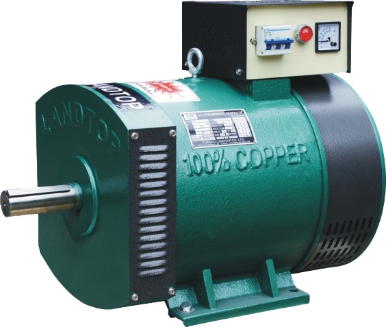
ST/STC Series Single / Three Phase A.C. Synchronous Generator / Alternator
This series generators are to be used in town, countryside, worksites, mountain and pasture as electric power source for lighting purpose, it can also he used as reserved power source for emergent case using. both of them have Excellent dynamic performance, convenient and reliable in operation. These generators are excellent in appearance and easy to maintain. Dimensions are adopted according to I.E.C Standards.

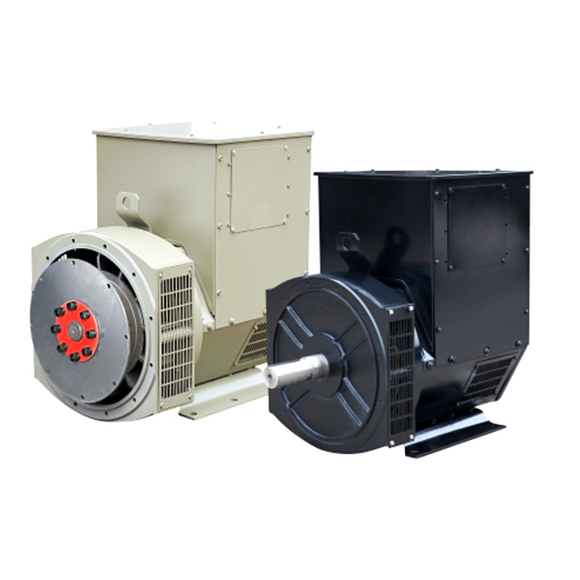
LTP Series brushless three phase A.C. Synchronous Generator /Alternator
♦ Brushless AC single or Three Phase Generator head for engine
♦The voltage from 110V-690V(3 phase)/ 110V - 240V(1 phase) , can be adjusted up slightly.
♦Insulation Class H, IP23 Ingress Protection.
♦Shunt excitation with AVR SX460
♦Single bearing and double bearing can be choosed
♦100% copper wire and 100% output, 2/3 pitch winding

Ac Generator,Alternator Generator,Ac Alternator,Ac Generator Motor
FUZHOU LANDTOP CO., LTD , http://www.landtopco.com